An overview of the OpenSS7 STREAMS protocol stack is illustated in Figure 2, below.
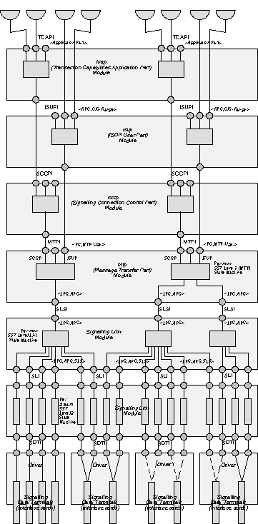
Figure 2. OpenSS7 STREAMS Protocol Stack
SS7 calls the device which terminates to the physical signalling data link (SDL) a signalling data terminal (SDT).
The Signalling Data Terminal Driver use the Communications Device Interface (CDI) specified in file <sys/cdi.h>. This is a specification for a general purpose OSI communications device for STREAMS and, because SS7 signalling data terminals are HDLC terminals, the model is reusable for signalling data links. The application of the CDI specification to the SS7 Signalling Data Terminal is detailed in the section on Signalling Data Terminals.
There are two kinds of signalling data terminal (SDT) driver: a class/type 1 driver (single channel) which has its PPA implicitly identified on open and which does not need CD_ATTACH_REQ to assign PPA, and a class/type 2 driver (multiple channel) which must have it's PPA identified with a CD_ATTACH_REQ with a PPA address of the appropriate type.
Examples of Signalling Data Terminals and types are illustrated in Figure 3.
Illustrated at (A) in Figure 3 is an example of signalling data terminals (interface cards) which have a single signalling data link (channel) associated with the device. In this example, a major and minor device number is associated with each instance of an interface card. By opening a specific major/minor device, the PPA (physical appearance) and signalling data link is uniquely identified. This is an example of a Type 1 signalling data terminal. This approach would typically be used for a hard configured (e.g. DIP switch) ISA device whose hard configuration can be used to uniquely identify the signalling data link (channel) concerned.
Illustrated at (B) in Figure 3 is an example of signalling data terminals (interface cards) which have a multiple (2) signalling data links (channels) associated with the device. In this example, a major and minor device number is associated with each instance of an interface card and with each channel on the card. By opening a specific major/minor device, the PPA (physical appearance) and specific signalling data link is uniquely identified. This is another example of a Type 1 signalling data terminal. This approach, again, would typically be used for a hard configured (e.g. DIP switch) ISA device whose hard configuration can be used to uniquely identify the signalling data link (channel) concerned.
Normally Type 1 devices would be opened by the SS7 configuration daemon using an entry under /dev for each device.
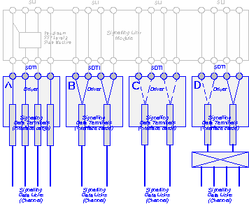
Figure 3. Signalling Data Terminal Examples
Illustrated at (C) in Figure 3 is an example of signalling data terminals which have multiple (2) signalling data links per card. In this example, it is not possible (or it is not necessary) for the driver to determine a priori which device is associated with a major/minor device number. This may be because the card's system configuration (ioports, irq, dma) depends upon the presence, absence or failure of one or more other cards at boot time (e.g. a PCI card which is configured depending on how the kernel walks the PCI bus at boot time). This is an example of a Type 2 signalling data terminal. This approach would typically be used for soft configured (e.g. PCI) devices where some external identifier (e.g. MAC address, serial number, pci slot location) must be used to attach the device.
Illustrated at (D) in Figure 3 is an example of signalling data terminals which not only have multiple (e.g. 24) channels per card, but there is a switching matrix between the card channel and the actual signalling data link which must also be configured. In this example, it is not possible for the driver to determine a priori which signalling data link is associated with a major/minor device number. This is because the cross-connect matrix has not yet been configured and any signalling data terminal could possibly be associated with any signalling data link. This is another example of a Type 2 signalling data terminal.
Normally Type 2 devices would be opened by the SS7 configuration daemon using a clone entry under /dev for the device major number and a CD_ATTACH_REQ would be issued with the desired PPA on the open file descriptor to associate the descriptor (and possibly the signalling data terminal through cross-connect matrix commands) with the required signalling data link appearance.
The SS7 configuration daemon must have a way of mapping a unique signalling data link address (local point code, adjacent point code, signalling link code) with a /dev entry (major/minor device number) or PPA for the specific device. This is performed by the system administrator in the SS7 configuration daemon's configuration file.
PPAs for Type 2 devices are device specific, yet are specified in the SS7 configuration daemon's config file.
When the SS7 configuration deamon is setting up Type 1 devices, it may still call the device's clone as long as the device is willing to identify itself (by PPA) when issued a CD_INFO_REQ primitive. Type1 cards should return an <interface number, channel number> which is derived from the device's hard configuration data (e.g. ioport, PCI slot number, etc.) which can be traced to the physical attachment point of the signalling data link in a CD_INFO_ACK primitive when issued a CD_INFO_REQ primitive. This will allow the SS7 configuration daemon to push a Signalling Link module and link the stream to a Signalling Link Set multiplexor and link the Signalling Link Set multiplexor to a Message Transfer Part multiplexor.
The SS7 Signalling Link Module provides the SS7 Level 2 (Signalling Link) state machine behavior such as specified in Q.703, T1.111 and ETSI ETS 300 008-1. This state machine behavior is common to all SS7 signalling links and depends only upon the capabilities of the CDI interface to the Signalling Data Terminal Driver. The SS7 configuration daemon pushes a cloned instance of this module onto each Signalling Data Terminal driver which it opens (drivers are listed in the daemon's config file or provided to the daemon at run-time). The module is either pushed explicitly by the daemon or is configured on the driver's autopush list.
The resultingstreams module arrangement is illustrated in Figure 4, below.
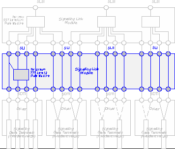
Figure 4. Signalling Link Module Overview
The Signalling Link Module is not a full Layer 2 OSI implementation: it only implements the lower half of OSI Layer 2. As such, it implements parts of the CDI, yet provides additional protocol-specific primitives for interacting with the Signalling Link Set module (the upper half of OSI Layer 2). The mapping of CDI primitives to Signalling Link primitives and the SS7 protocol-specific primitives which the Signalling Link module provides are detailed in the section on Signalling Links.
Because there is a one-to-one relationship between an instance of the Signalling Link module and an instance of a Signalling Data Terminal, the Signalling Link module relays CD_ATTACH_REQ and CD_ATTACH_ACK primitives to and from the Signalling Data Terminal. This permits the module to be configured as an autopush module for the Signalling Data Terminal, yet still permits the SS7 configuration daemon the ability to attach Signalling Data Terminal Drivers to specific PPAs (Type 2) or discover the PPA of the driver (Type 1).
The Signalling Link Set module is a multiplexor which is used to group streams associated with signalling links into a signalling link set. Signalling link sets can consist of one or upwards of 16 signalling links. Signalling Link Set modules fan-out downstream and fan-in upstream. Each signalling link set multiplexor is associated with a single Message Transfer Part multiplexor.
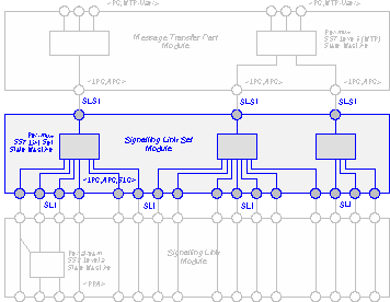
Figure 5. Signalling Link Set Module Overview
The Signalling Link Set module completes the OSI Layer 2 capabilities and, as such, presents a DLPI interface upwards. The DLPI interface has been extended to permit configuration and SS7 protocol specific information to be exchanged between the Network Layer (MTP) and the link set. The details of the DLPI mapping and the extensions for the SS7 protocol are provided in the section on Signalling Link Sets.
The Message Transfer Part module is a multiplexor which is used to group collections of signalling link sets into a network nodal function and implement the MTP L3 state machines such as those of Q.704, T1.111.3, and ETSI ETS 300 008-1. The MTP multiplexor fans-out downstream by signalling link set and fans-out upstream by MTP-user type.
The Message Transfer Part module provides OSI Layer 3 capabilities and, as such, presents a XNI interface upwards. The XNI interface has been extended to permit configuration and SS7 protocol specific information to be exchanged between the Network Layer (MTP) and the Transport Layer (SCCP and MTP-Users). The details of the XNI mapping and the extensions for the SS7 protocol are provided in the section on Message Transfer Part.
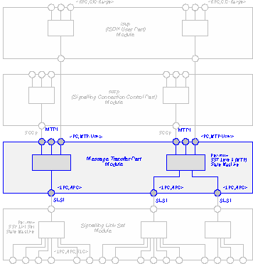
Figure 6. Message Transfer Part Overview
The SS7 configuration daemon opens a control stream and configures a multiplexor by linking signalling link sets to the MTP module for each configured MTP nodal function. The SS7 configuration daemon's config file provides information about which signalling link sets are connected to which message transfer parts.
The Signalling Connection Control Part (SCCP) module is used to provide transport layer services above the network layer (MTP). The SCCP module has a one-to-one correspondence with an MTP node downstream and fans-out upstream by SCCP-user.
The Signalling Connection Control Part (SCCP) provides OSI Layer 4 capabilities and, as such, presents an XTI interface upwards. The XTI interface has been extended to permit configuration and SS7 protocol specific information to be exchanged between the Transport Layer (SCCP) and its user applications (e.g. TCAP). The details of the XTI mapping and the extensions to the SS7 protocol are provided in the section on Signalling Connection Control Part.
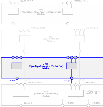
Figure 7. Signalling Connection Control Protocol Overview
The SS7 configuration daemon opens an MTP stream and binds it to the SCCP MTP-user for each MTP nodal function equipped with SCCP according to the config file and pushes an SCCP module onto the bound stream. The SCCP module must be configured by the SS7 configuration daemon with rather detailed static Global Title Translation (GTT) routing information which the daemon obtains from special GTT translation tables which have been configured by the system administrator.
SCCP (and other MTP) users can open streams on the SCCP (or MTP) module by calling the SCCP (or MTP) clone device and binding the stream to an SCCP Called Party Address (or MTP Point Code and User).
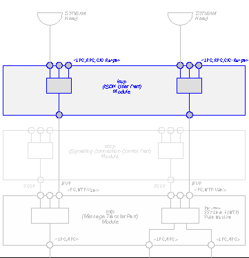
Figure 8. ISDN (Integrated Services Digital Network) User Part Overview
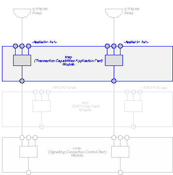
Figure 9. Transaction Capabilities Application Part Overview